Wideband MVDR Beamforming for Pixel-Based Reconstruction in Ultrasound Imaging
- Type of project: Research Project/Hauptseminar/Internship (literature review + coding)
- Contact: ozan.cakiroglu@tu-ilmenau.de
In pulse-echo ultrasound imaging, the conventional reconstruction algorithm is the Delay-and-Sum (DAS) Beamformer, which adjusts the delay of each channel to align pulse echoes returning from each scatterer. However, the DAS beamformer does not aim to reduce noise and interference components on the received data of each channel but focuses the beam on each single candidate pixel point. The Minimum Variance Distortionless Response (MVDR) beamformer goes beyond the basic DAS approach by optimizing the weights applied to the received data of each channel to achieve better performance in terms of signal-to-noise ratio (SNR) and interference suppression. In this task, it is asked to implement a wideband MVDR beamformer by completing the following steps.
Implementation Steps
-
Presteering: MVDR beamformer needs the wavefront of the pulse echo responses to be a plane wave, which is not the case in near-field ultrasound imaging. However, applying the appropriate delays, focusing each received signal to the candidate pixel as in the DAS beamformer, the plane wave, which is parallel to the transducer surface, can be created.
-
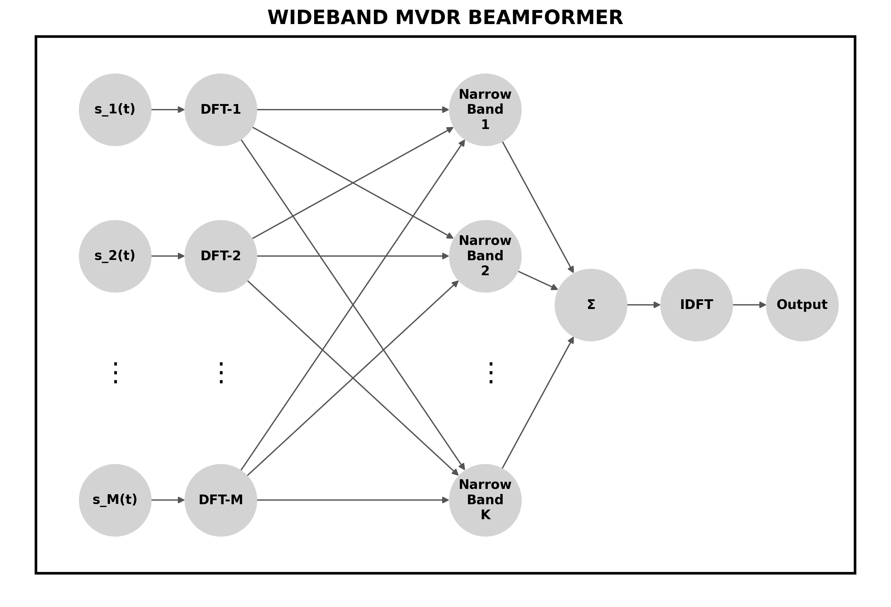
Division of Received Data into Subchannels: The second assumption of the MVDR beamformer is the narrowband assumption, which assumes that the envelope of returning signals does not vary as much as the center sinusoidal. It ensures that the only varying parameter between recorded signals in the adjacent transducer elements is the phase difference. However, wideband signals are typically used in ultrasound imaging, so these signals must be split into subchannels to meet the narrowband assumption.
-
Spatial Covariance Matrix with Spatial Smoothing: The spatial covariance matrix of each subchannel data in each transducer element should be calculated in the frequency domain. In calculation, spatial smoothing should be applied, which involves dividing the array into overlapping subarrays and averaging the covariance matrix over these subarrays.
-
Calculation of MVDR beamformer weights and reconstruction: MVDR beamformer weights should be calculated by applying the MVDR formula asking for steering vector and sample covariance matrix. The steering vector should be all one vector since the presteering stage ensured that the incoming wave is parallel to the surface of the transducer. After detecting weights to each subchannel, MVDR beamforming can be realized by summing up weighted received signals across all received channels. The inverse FFT of the resulting vector gives the beamformed time-domain output signal. The reconstruction for the candidate point can be realized by summing up all elements of the beamformed output.
-
Image Reconstruction: The initial 4 steps should be repeated for each candidate pixel point in the measurement area to reconstruct whole ultrasound image.
Related Works
- I. K. Holfort, F. Gran and J. A. Jensen, “Broadband minimum variance beamforming for ultrasound imaging,” in IEEE Transactions on Ultrasonics, Ferroelectrics, and Frequency Control, vol. 56, no. 2, pp. 314-325, February 2009
Requirements
- Solid knowledge in linear algebra and signal processing
- Python programming
- Being a master’s student.